Ningún producto
A determinar Transporte
0,00 EUR Total
Estos precios se entienden sin IVA
¿Buscas un repuesto de copiadora o buscas una de ocasión y no la encuentras? Consúltanos.
Compramos cartuchos vacíos de Xerox Versant
Chips intec CP2020 XP2020 | Cartuchos Intec CP2020 XP2020 | Recargas Intec CP2020 XP2020 | Tambores, fusor, cinta, fusibles etc. |
 470,00 EUR (IVA excl.) |  26,00 EUR (IVA excl.)  25,90 EUR (IVA excl.)  39,00 EUR (IVA excl.) |
Nuestra tienda usa cookies para mejorar la experiencia de usuario y le recomendamos aceptar su uso para aprovechar plenamente la navegación.

Publicado el : 24/09/2017 18:35:58
Categorías : Trucos

For assembling stage you need:
- solderer and solder alloy
- multimeter instrument
- 25-conductor flat cable, 1 meter, (it is possible to use part of more wide flat cable)
- DI-25m connector (25 contacts, male, with flat cable mount)
- small wiring board
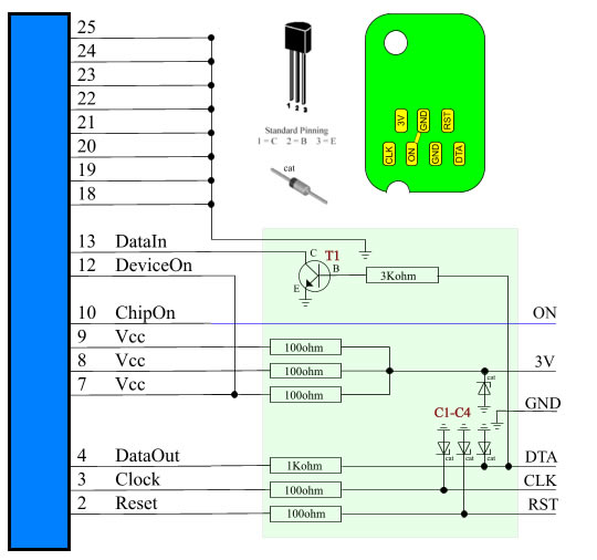
- 7 resistors (rated values are depicted on electric circuit)
- 4 Zener diodes C1-C4 (stabilitrons, use any 0.5w, 3.3v, like BZX55C 3V3)
- 1 transistor T1 ( BC546C, BC547C or similar ones)
- RJ45 socket
Below you'll find electric circuit of add-on device.
Wiring board is marked by semitransparent light-green color.
On picture you'll find pinout for all used components.
Insert flat cable (use approx. 0.5m) in connector mount and fix it.
Solder all circuit on wiring board.
Now solder flat cable from connector and small flat cable (about 0.3m) what'll lead to chip contactor.
Study how chip contactor looks like in your printer head.
Using suitable RJ45 socket it is possible to make some resemblance of original contactor by slightly breaking socket,
then by cutting and bending necessary thin springy contacts similarly to original contactor. Then you must solder small
flat cable to contactor. Use contacts pinout shown on chip picture.
For users of C42 or similar printers, with small flat cable leading to chips. You can buy similar flexible flat cable and use your
print head as contactor by removing original flat cable and inserting yours. Pinout for C42 flat cable : 1-RST,2-3V,3-DTA,4-GND,5-CLK.
It is possible to make contactor using socket contacts and piece of transparent plastic with small holes.
You you invented some other easy and suitable way to make good contactor, write us about it, we'll add your instructions here.
How to check assembled device
Do not try to test device with chip in contactor.
Connect your device to port. Select Auto in Port list.
Press Test button. Answer positively to program question about testing procedure.
Program will show you first message and ask to press OK.
Get your multimeter and measure voltage on small flat cable wires leading to contactor.
Measure voltage between RST and GND, 3V and GND, DTA and GND, CLC and GND.
Measured voltage must be around 0 v.
Press OK button.
Measure voltage between RST and GND, 3V and GND, DTA and GND, CLC and GND.
Measured voltage must be higher then 2.9 v. If measured is lower then required you can get errors working with chip.
Minimum voltage is common for DTA. If it is very low try to reduce correspoding resistor value.
Press OK button.
Run test another time. In this time look at the value placed after Readed word.
This value must be 1 in first message and 0 in next.
All further testing must be performing with chip in contactor. Use check chip operation.
Read error indicates wrong device functioning.